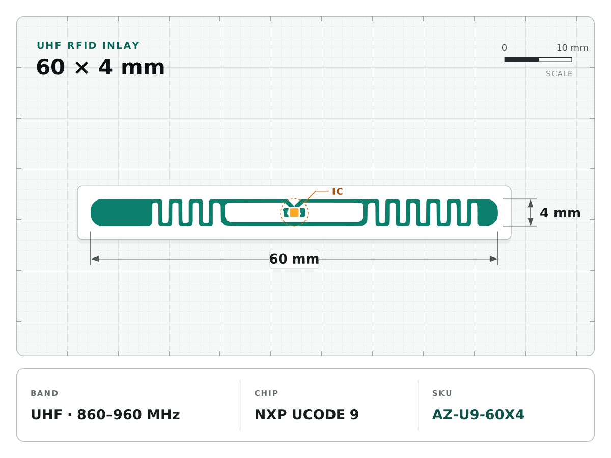
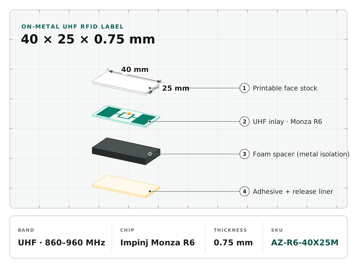
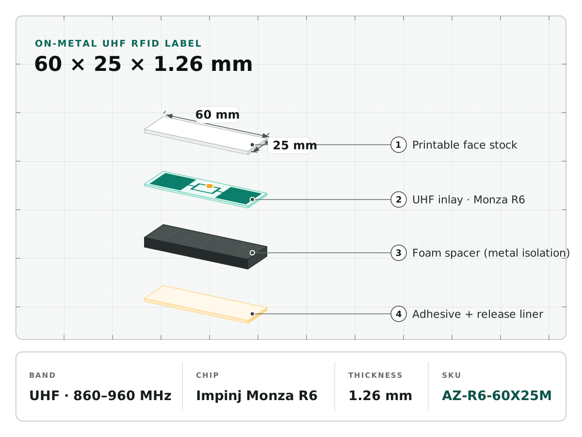
An ordinary UHF inlay placed directly on metal can detune and lose useful performance. An on-metal tag is designed around that mounting condition. Its spacer, conductor and adhesive stack are part of the RF design, not interchangeable packing materials.
Choose the construction for the job
| Construction | Useful starting point | Acceptance focus |
|---|---|---|
| Flexible spacer label | Flat indoor assets and printable identification | Adhesion, thickness, printer handling |
| Rigid or encapsulated tag | Mechanical exposure and permanent attachment | Fixing, housing, cleaning and impact |
| Specialist high-temperature tag | Defined thermal process | Complete-tag exposure evidence |
Antenza’s on-metal label catalog covers flexible structures. Do not transfer their specifications to a rigid outdoor tag or a high-temperature part label. Ask for a separately qualified construction where the service environment requires it.
Dimensions are an engineering constraint
Give both available footprint and acceptable thickness. Increasing one dimension or spacer thickness does not guarantee a proportional range gain: tuning, metal size, edge placement and reader geometry interact. Compare a size ladder on the same representative asset instead of choosing by area alone.
If a fleet contains plastic and metal assets, test appropriate structures for each while maintaining a common identity scheme. A standard UHF inlay may serve the non-metal assets more efficiently.
Placement changes the result
Test the intended position before final artwork. Include edges, curved areas, seams and nearby hardware. Prepare the surface using the adhesive supplier’s method and allow the specified dwell time. Check reading performance before and after the relevant cleaning or temperature cycle.
Where a label is recessed or partly covered, reproduce that condition during trials. An open-air demonstration on a large flat plate is not proof of performance inside the final assembly.
Check printer and encoding compatibility
The roll must fit the printer mechanically and place the target inlay in its RF encoding zone. Request a trial roll at the proposed pitch and winding direction. Read back the encoded identities and confirm adjacent labels are not written accidentally. Thick media may require a printer-specific on-metal configuration.
Approve a complete sample, not a chip name
Record chip, dimensions, construction, mounting position, reader region and acceptance result. Confirm supply status for legacy chips before fixing repeat-order specifications. A replacement chip or changed spacer requires revalidation.
Send the asset material, allowed area, environment and printer model through the engineering inquiry form. We can select sample candidates for the actual mounting surface rather than guessing from a catalog distance.